DIY TV Ambilight
What is it?
The Phillips Ambilight system will take what’s showing on screen and light up behind the TV to give a more immersive feel. You can see this in action on the video below.
As always, I wanted to make my own! It’s more fun than off the shelf solutions and often works out cheaper. You also learn something new in the process!
These builds are well documented, so I won’t go into too much depth on each step. Just some insightful information.
The Hardware
Overview
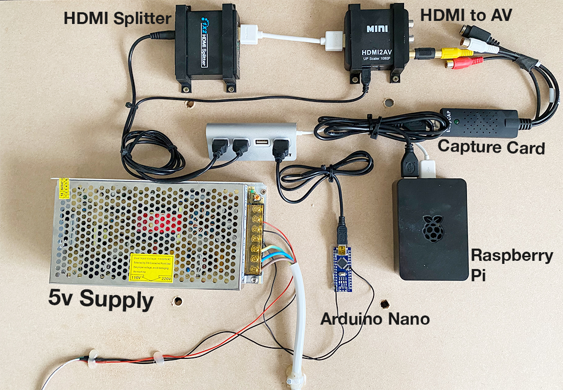
Capture Card
First we need a way of detecting what’s on the screen. To do this we’ll take the HDMI (in my case from a Fire Stick) and split it. One output goes into the TV, as normal. The other is what we use to capture and analyse. For this you can use a HDMI capture card, or you can do what I did and convert the HDMI to AV and then use a cheap AV capture card. Either option works!
Processing
The Raspberry Pi is then the main part of this project. It’ll take the video feed through the capture card, analyse the edges of the screen and calculate which LEDs to light up and what colours. For this i’m using a Raspberry Pi 3 that I had spare.
The Arduino is then used for real-time control of the LEDs, connected to the Raspberry Pi via USB. Having the Raspberry Pi do communication with the LEDs and analysis of the screen results in flickering LEDs and other issues. This interfaces with the LED strips through a single digital pin and ground connection to the LED strip power supply.
LED Strip and Power
For LED strips I would recommend the highly popular WS2812B. For a 50" TV, 4m is a perfect choice and left me with some spare. You can get them in 30, 60 or 144 LEDs/meter. Consider that the more LEDs, the bigger your power supply needs to be. I opted for the middle ground 60 LEDs/meter.
For power I used a 5v 18A supply I had lying around. This connects directly to the positive/negative connectors of the LED strip.
If you want to accurately calculate the power draw, each RGB LED will consume 50mA when set to white and full brightness. This is because internally the RGB LED actually contains 3 LEDs (red/green/blue). When you want white, what actually happens is the red/green/blue LEDs are all ‘blended’ together to form white. So when we want full white brightness, every LED has to be powered, compared to if we wanted a single colour.
With 60 LEDs/meter at 4m that’s 240 LEDs. At worst case scenario that would be
240 LEDs * 0.05A = 12A
So we would need a power supply greater than 12A to handle this LED setup. As a quick comparison, 144 LEDs at 4m would be a whopping 28.8A!
The Software
Raspberry Pi
This part is easy, for the Raspberry Pi you can simply install Hyperion OS. The provided documentation is fantastic and it’s quick to setup. Once you have it installed, it’s a matter of configuring how many LEDs there are, the type and what the capture method is.
Once installed:
- Access the installation through http://YOUR_RASPBERRY_IP:8090
- Navigate to Configuration > LED Hardware
- Set Controller Type to ws281x
- Set Hardware LED Count to the amount of LEDs you have
Note: If your colors are not correct, try tweak RGB Byte Order. Some LED strips have R/G/B in different orders.